This post is from a suggested group
v1.1.6 Sensor Calibration

Hi,
PDM15 (v1 I believe) with v1.1.6 SW with a Rife analog temp sensor connected to an input. How do you get Sensor Calibration tables to work? I have it configured but it always outputs 0. I tried fudging it with a 2D table which did work, which makes me think it's a bug in v1.1.6?
Thanks
Simon
108 Views


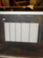
Hi, Can you make sure that the last few values are filled in on the sensor calibration table